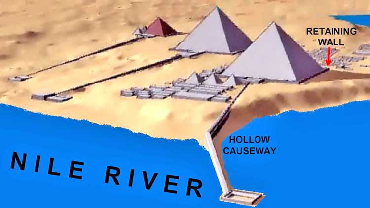
INTRODUCTION

Each of us is given a piece to some grand puzzle of life. I was given the opportunity to demonstrate that there was a water machine under the Great Pyramid and the water machine produced the sonic force to drive the Great Pyramid. Edward Kunkel1 was given a piece with his vision of the Great Pyramid being a water machine – a water pump. Chris Dunn2 was given a piece with his vision of the Great Pyramid being a sonic machine - a power plant. Stephen Mehler3 was blessed by receiving indigenous teachings. His teacher, Hakim, related that the Great Pyramid was a sonic machine that ran on water. Joe Parr has done extensive testing on the pyramid's shape effect.

Edward Kunkel tried to incorporate all of the rooms and shafts into the water machine. This was a grievous mistake that haunted him. Chris Dunn’s work focused primarily on the upper rooms and shafts. He described he subterranean chamber as having housed the equipment that drove the pyramid to resonance. Hakim taught Stephen the existence of miles of water tunnels that connected all of the ancient civilization.

My research is the working proof that binds these visionaries. It includes the first and only working model of the subterranean section of the Great Pyramid. The whole pyramid can be removed and the subterranean section still runs. Because the model is mainly the subterranean section of the pyramid, it raises as many questions as it answers.

FIGURE 1. Giza Plateau Layout
 

(Left) The causeway from the Great Pyramid can be seen leading down to the location of the ancient Nile River. The causeway was a hollow structure nearly half a mile long. Why did they need this hollow structure? (Right) The retaining wall is an accepted part of the pyramid structure. This retaining wall would have been as high as the entrance door. What did it need to retain?
 

Back to Contents


THE CAMPS

Egyptology has been polarized into two primary factions. The Orthodox camp follows the standard version of history that claims the Great Pyramid was utilized as a tomb by Khufu5. Yet, no one has ever found any signs of a non-intrusive burial within any pyramid2,3,5. The only sign that the Great Pyramid was even related to Khufu is a glyph in an upper chamber that was most likely forged by Perring3. They view the entire subterranean section as a mistake. They believe the 1,200 square foot subterranean chamber was unfinished and left abandoned5. They acknowledge that the “Queen’s chamber” has nothing to do with any Queen. The granite box of the so called “King’s chamber” had no lid.

The Alternate camp is comprised of indigenous teachers, engineers, physicists, mathematicians, and architects.

The oral indigenous teachings state:

  • The pyramids were never intended as tombs.3

  • The pyramids are some type of sonic machines.3

  • The pyramids were in existence long before the time of the Pharaohs.3

  • Dynastic Egyptians merely lived in the presence of the pyramids just as we do today.3

Did these buildings actually come from an earlier time of a more advanced civilization?

Many modern day physicists and engineers view the Great Pyramid as a machine. They show physical evidence to reinforce their claim:

  • The shape has been shown to have dramatic energizing effects. An example being water does not freeze at - 40° C. within a pyramid structure.18

  • The King‘s chamber has been expanded and the granite ceiling beams are fractured due to some type of massive internal explosion.2

  • The granite coffer has changed from pink to brown due to high temperatures.2

  • The granite coffer and many remnants around the Giza plateau had been machined with some type of triple axis mill, an advanced machine.2

  • Acoustic engineers are demonstrating that the King‘s chamber and the coffer are actually tuned to resonate at a specific frequency - 440Hz.2,3,10

  • The Queen‘s chamber had an inch of salt encrustation on the walls and ceiling possibly due to a chemical reactions within the room.2

Many mathematicians embrace the building. They show that it incorporates numerous advanced mathematical relations within its design:

  • The perimeter is equal to a half minute of equatorial longitude or 1/43,2000 earth’s circumference. The height is 1/43,200 earth’s polar radius.2 Did they know the Earth’s circumference?

  • The base of natural logarithms, e, is incorporated in the primary angles.16 Natural logarithms weren’t even discovered until the 1700’s by Euler. How did they know this number?

  • The number pi is found when taking perimeter and dividing by 2 times height.2

  • Our present day inch based directly on the pyramid inch, and is only 0.001” different.2

Many architects marvel at the size and precision of the building:

  • The Great Pyramid is the largest and most accurately constructed building in the world, ever.2

  • The building is almost perfectly aligned to the polar coordinates, built to within 3 arc minutes from perfection.5

  • The shear volume of blocks, estimated at 2,300,000 blocks, would require 33 quarries to work 24 hours a day for 27 years using modern machines.7

  • The five layers of granite beams of the King’s chamber ceiling weigh 70 tons each.2

  • The 13 acre base is level to within ¾”.5

  • The 756’ sides are equal to +/- 3”, which is far more accurate than modern building standards.5 Did they really use string to make these measurements?

  • The 330’ descending passage is straight to within ¼ inch for the entire length. One 90’ stretch is straight to within 1/10 inch.5

  • The casing stones are fit together with an accuracy of +/- 0.005”.5 Did they form these blocks with copper chisels and beating stones?

The Mystery schools (Masons, Rosicruscians, Templars, etc.) view the building as a sonic initiation machine that leads to higher knowledge.7 The Masons put the Great Pyramid on the back of the U.S. one dollar bill.
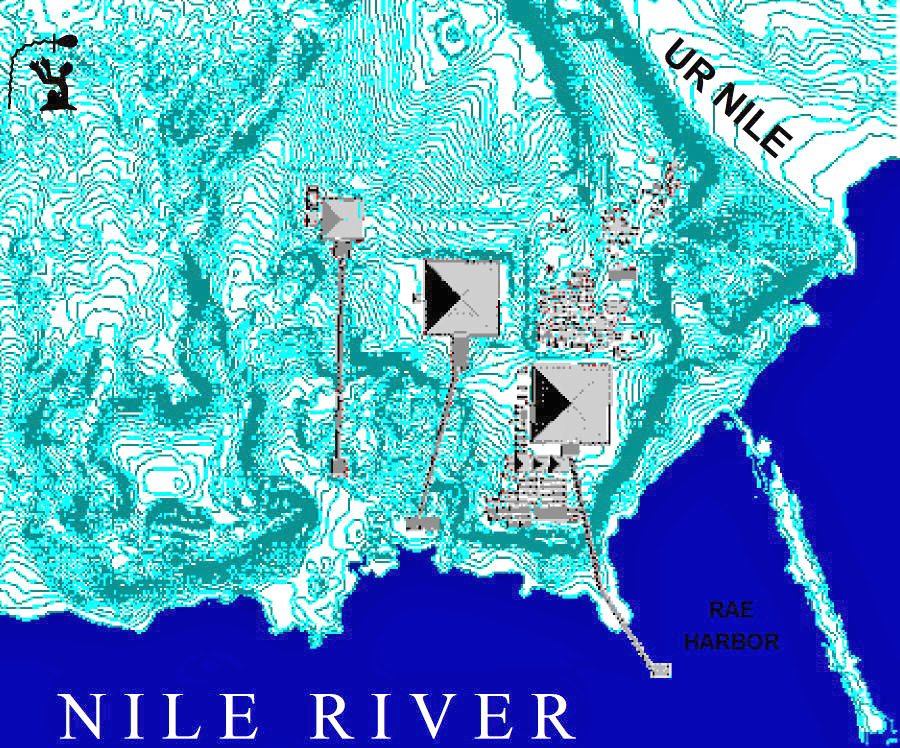
I have found a machine built into its lower extremities. I can show a working model of this machine. Is this mere coincidence that these parts can be used in some type of simple machine? What physical evidence supports this claim? We do find extensive water erosion patterns that exactly match the water flows of the machine.

FIGURE 2. Giza Plateau Topographical
 

The Nile River was a major factor for the Giza plateau design. Just as important as the Nile was the Western Nile (Ur Nile). The Western Nile was at a higher elevation and gravity fed many miles of underground aqueducts3 . One function of the aqueducts was to provide water to the Great Pyramid’s moat.
 

Back to Contents


THE HYDRAULIC RAM PUMP

Before any theorizing about the Great Pyramid, a little pump background is helpful. Invented in the 1700’s, hydraulic ram pumps are a primitive but highly effective machine. These simple pumps incorporate only two moving parts. Used extensively around the world until the invention of the electric water pump, these pumps have nearly been forgotten. The basic design utilizes the force of falling water to elevate part of the water (see Figure 3). Water flows down the drive pipe into the compression chamber.


Water escapes from the waste valve until the water‘s velocity forces the valve shut. When the valve shuts, the water stops flowing instantaneously and causes the water to compress resulting in a compression wave, or shock wave, to emanate from the valve area. In the drive line, the water reverses direction until the shock wave reaches air and returns down the pipe.


In the output line, a high pressure surge passes through the check valve. This surge is at least fifty times (3,360 psi at Giza) the static water pressure of the compression chamber. When the compression wave leaves the compression chamber, a low pressure situation exists. The low pressure is equal and opposite to the compression wave. This immediately re-opens the waste valve. The stand pipe is a shortcut for the compression wave to reach air. Once the compression wave reaches air, a wave returns down the stand pipe and starts the water flow back into the compression chamber. The stand pipe, usually twice the diameter of the drive pipe, allows for the highest possible cycling rate.

Most hydraulic ram pumps are free standing, with the majority of parts being exposed above ground (see Figure 3). A specialized application is to have the lines underground (see Figure 4). The stand pipe needs to exit to air, and the waste valve (wastegate) also needs an exit. To facilitate the waste valve output, a line may be extended from the compression chamber to an appropriate location. This allows for the bulk of the pump lines to be centrally located. This layout has an interesting side effect - the compression wave becomes focused in the line leading to the compression chamber and this focused compression wave transmits a pulse through the compression chamber’s ceiling.

FIGURE 3. Standard Hydraulic Ram Pump
 

The basic hydraulic ram pump has water running from the elevated water source to the compression chamber. A valve in the compression chamber allows water to flow out until the velocity forces the valve shut. The valve shutting causes a high pressure spike that forces water past the check valve and through the output line. The waste valve reopens and once again allows water to flow down the pipe. The stand pipe affects the cycle rate by creating a shortcut for the reverse surge.

FIGURE 4. Specialized Application Hydraulic Ram Pump
 

Building an underground ram pump requires lengthening of the compression chamber to allow for waste water output. The output line is placed on the ceiling of the compression chamber to automatically remove air from the chamber. The line from the waste valve to compression chamber acts as a wave guide, effectively focusing the shock wave into a pulse. This pulse impacts the compression chamber’s ceiling effectively transmitting part of the pulse vertically and reflecting part of the pulse back down the waste valve line. Design: John Cadman

FIGURE 5. Confirmed Existence at Giza
 

Before theorizing about missing parts, it is important to view what is known to have existed. Although the retaining wall (1) no longer is in existence, it is an accepted part of the complex. The retaining walls and casing stones were dismantled for building materials.
 

Back to Contents


THE MYSTERY ROOM

The subterranean chamber (6) is the largest and most unusual room of the Great Pyramid. This odd looking room is located 100’ below the base of the Great Pyramid and carved from the solid limestone bedrock of the plateau (see Figure 5). This large room is 27’ north to south and 56’ east to west. The entrance is near the floor at the northeast corner. The eastern half of the room averages 11’ to 13’ in height. The western half of the room is a 5 ½’ high step (see Figure 6). The step has a channel in the middle that leads to the western wall. This channel, the “step channel“, starts at floor level but tapers as it heads towards the back wall.


On top of the step are two fins that run from the front of the step to the back wall. A third fin starts ½ way back on the step. All of the fins run east to west and reach up near the ceiling. On the main floor there is a {6’} wide square pit set diagonally some 5’ from the eastern wall. This pit drops 5 ½‘ to a step where the pit narrows to 4’ square. The total depth of the pit is about 11’ although Cavigula had drilled down another 30’ in the 1800’s.5 In the southeastern corner is the entrance to a tunnel that measures 29” by 31”. Dubbed the ”dead end” shaft, this tunnel runs 57’ due south where it ends in a vertical wall.
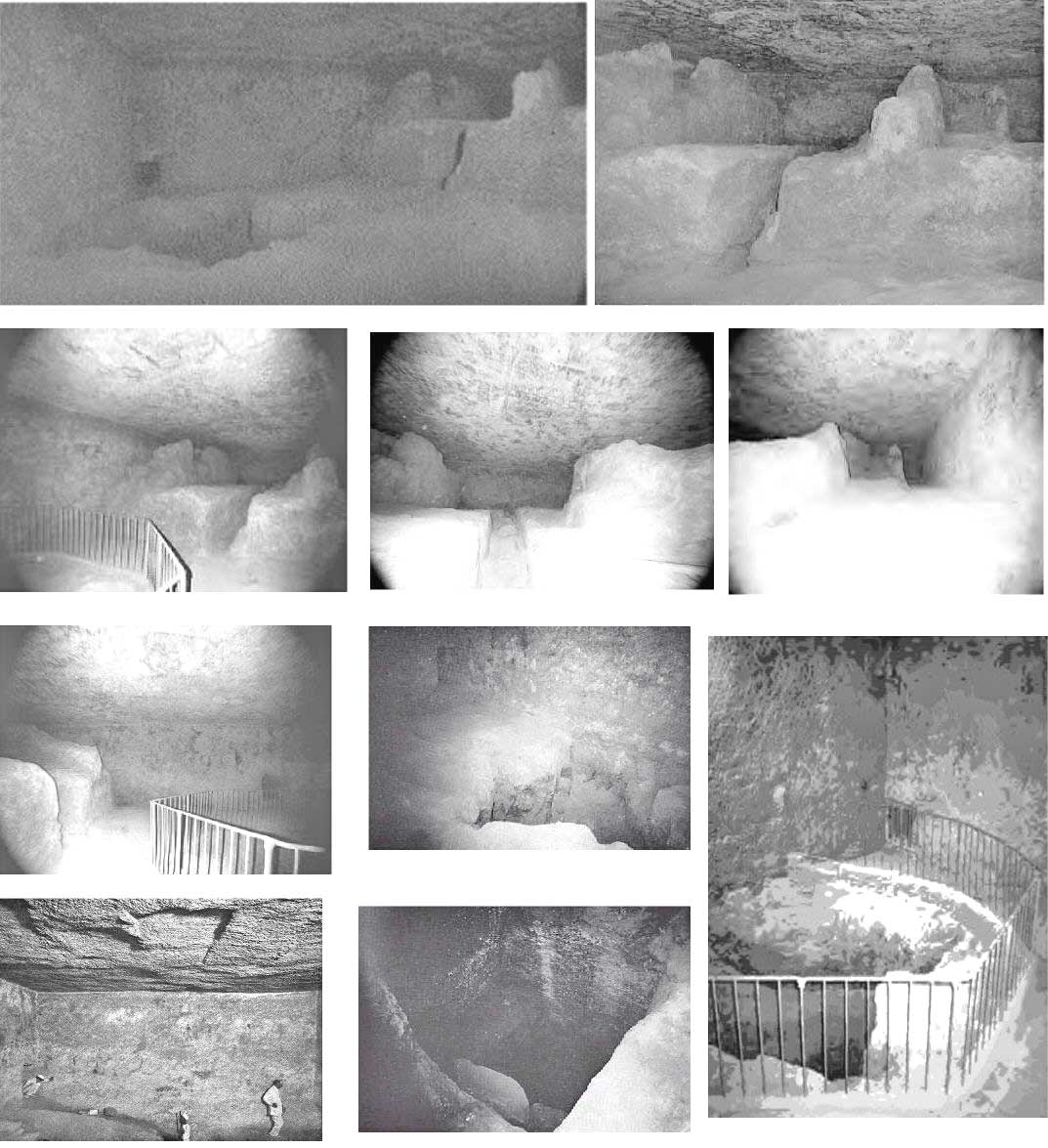
The subterranean chamber has confounded most pyramid researchers. The Orthodox camp essentially gave up trying to explain this room. They came up with the idea that the whole subterranean section was a giant mistake. Edward Kunkel, Chris Dunn, and Joe Parr gave alternate views. Kunkel was partially correct when he recognized that the chamber was part of a modified hydraulic ram pump. Dunn recognized that the chamber must be the location for the source of a pulse direct towards King’s chamber. Parr recognized that it was the location of a sound transmission that energized the pyramid.

FIGURE 6. Views of the Subterranean Chamber
 

It is difficult to describe the largest room of the Great Pyramid. Upon entering the room we are faced with a pit tunneled in the middle of the floor. One half of the room is a large step with odd fins. The handrail around the pit was added in modern times to prevent visitors from falling into it. Photos: Guardian’s Giza, Edgar Brothers, GPG-RA

FIGURE 7. The Subterranean Chamber Layout
 

Although these drawings were a primary source for the models, they have errors in the finned area and the pit’s relative angle. The fin errors were a result of the fins being filled with rubble. The pit is also rotated slightly from it’s diagonal offset. The bottom drawing shows the location of the small recess that corresponds to the best location for an air or gas removal line. The blocked line leads up into the pyramid with the best output being the Queen’s chamber niche.
 

Back to Contents


A MODIFIED HYDRAULIC RAM PUMP AT GIZA

The pyramid had a tall masonry enclosure that was higher than the pyramid’s entrance (1) (see Figure 8). Water was flooded between this masonry wall and the pyramid via tunnels from the ancient Lake Moeris (2). Lake Moeris and the Western Nile were at higher elevations and allowed for water tunnels to gravity feed to this pyramid’s moat1,3 (see Figure 2). One of the water tunnels existed as a “well” in front of the pyramid’s entrance. This well has since been covered with pavement1. As the moat filled, water flooded the entrance and ran down the descending passage (3) into the subterranean chamber (6).

FIGURE 8. The Basic Passage Layout
 

The pump assembly incorporates the descending passage (3), subterranean chamber (6), the “dead end” shaft (7), the pit (8), the well shaft (4) and grotto (5). To complete the basic hydraulic ram, two blocked tunnels need to be cleared. At the end of the “dead end” shaft exists a plane surface that correlates to the backside of a check-valve. The pit hasn’t been completely cleared of rubble to expose the horizontal shaft, yet. In the running model the water in the well shaft pulsed at the grotto height even though this is below moat elevation.


At the lower end of the descending passage a tunnel leads up towards the lowest of the two upper rooms. This shaft is known as the “well shaft” (4). Until the late 1800’s most of the descending passage, the lower part of the well shaft and the subterranean chamber had been buried for a thousand years2. Indigenous teachings state emphatically that there is still a buried tunnel that leads from the bottom of the subterranean chamber’s pit (8) (see Figure 8) to the location of the ancient Nile River3.


This tunnel was a drain that had a mechanical element at its end. This mechanical element is possibly a sliding stone plug, which opened and closed causing a pulsing action (see Figure 24). The “dead end” shaft (7) terminates 57’ past it’s entrance. It is my hypothesis that the termination is the back face of a closed check valve, and a tunnel exists beyond (see inset Figure 8).

To maintain consistent pulse timing, the pyramid’s moat requires a specific static level. To ensure this, the moat is provided more water than is consumed. The excess water was removed by the causeway running down to the Nile River (see Figure 1).
 

Back to Contents


SUBTERRANEAN CHAMBER MODELS

Model construction started in June of 1999. I was very surprised to find that every source of subterranean chamber dimensions and drawings had omissions or errors. This room has been bypassed when compared to the upper chambers that have been measured and documented extensively. This may have been the result of the Greco-Roman tradition of the pyramid being a tomb and the subterranean chamber being an unfinished room3.


A model was built drawing upon the Edgar brothers’ sketches8 (see Figure 7), Flinders Petries’ dimesions9, Edward Kunkel’s drawings1, and every photograph I could find. Photographs played a crucial part in verifying details on various drawings. A 1:48 scale was decided upon. This scale utilizes ¾”, 1” and 1 ¼” pipes. The subterranean chamber is 8” x 13” x 5”. By August of 1999 I had built a model as described by Kunkel. The first model leaked, cracked and, worst of all, didn’t run.

With too many hours invested to quit, the journey continued. The second model incorporated something that wasn’t in Kunkel’s design -.a line that went out through the bottom of the pit shaft. During the fall of 1999 I believed that the pit’s line was the pressurized output. I half heartedly continued model construction with the hopes that something would become of it (see Figure 9). To maintain focus, pictures of models 1 and 2 are not included.


Four months passed and then in the last hours of the millennium (New Year’s Eve 1999), I had a vision of the correct layout. With renewed excitement, model construction continued (see Figure 10). Within four months (April 3, 2000) I had constructed a working model that started running on the first try! (see Figure 11)

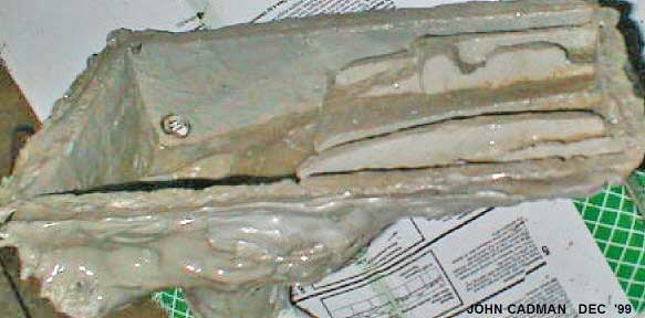
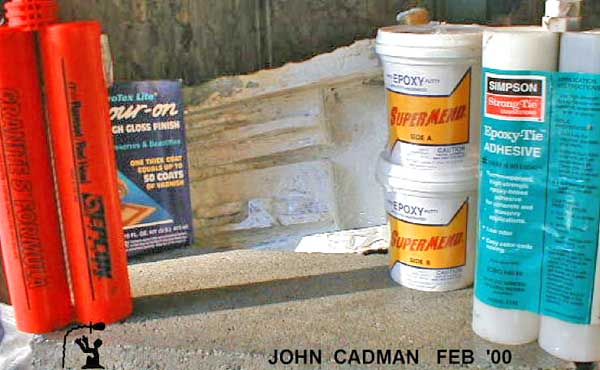
FIGURE 9. Model No. 3 Casting and Ceiling Installation
 

(Left) The model has been removed from the rubber mold, and it is ready for entrance and exit fittings. (Right) The ceiling block has been sealed by saturating it with clear epoxy resin. The model is then glued to the block with the a slightly pliable epoxy to absorb shock without cracking. The whole model is then covered with a mix of the two epoxies, fiberglass, and steel reinforcements. Corporate sponsorship would be welcomed . . . “The epoxy that built the pyramid”

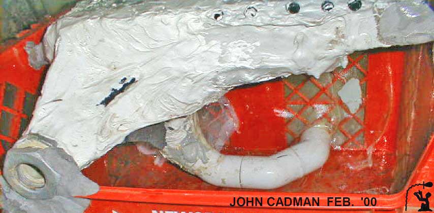
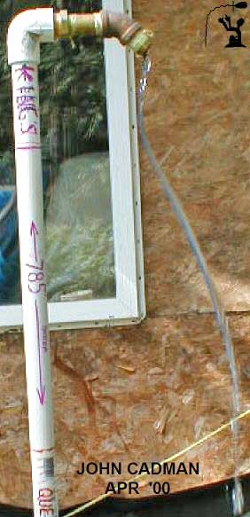
FIGURE 10. The Model Preparing for Cement
 

The model before cement was added. The pit shaft was angled west then south in this model for strength. At Giza the shaft goes due southeast. The model uses twin 45’s instead of single 90’s to mimic the 45 degree reflective elbow of Giza. (Right) The horizontal passage into the subterranean chamber model utilizes square interior to mimic the tunnel at Giza.

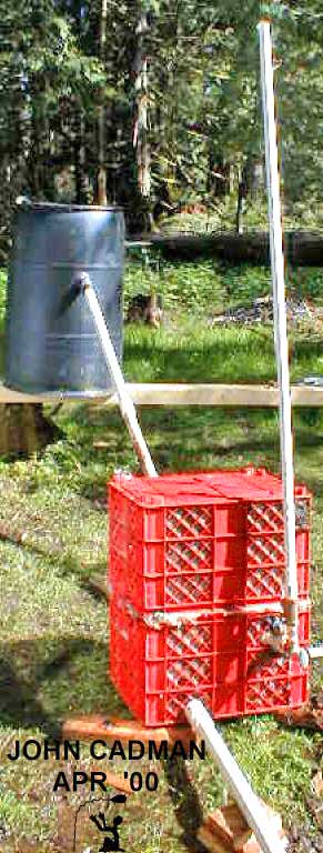
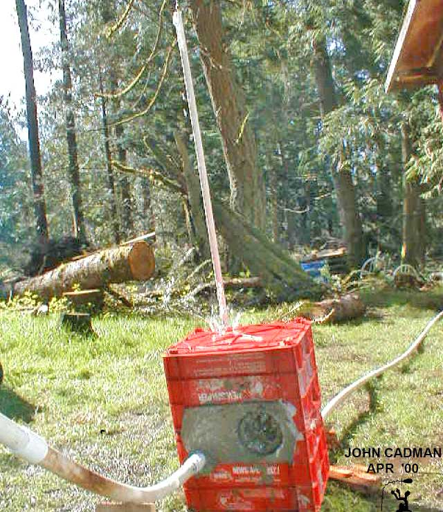
FIGURE 11. The First Working Model - April 3, 2000
 

(Left) Originally believing that water was pumped to the King’s chamber, the model is shown pumping to that elevation. (Center) A barrel was used for the reservoir, but filling limitations forced moving the model to a seasonal creek with a pond utilized for the reservoir. (Right) The model is housed within reinforced cement, while at Giza, the subterranean chamber is housed under 100 feet of bedrock. In either case, the room is situated to withstand shockwaves.
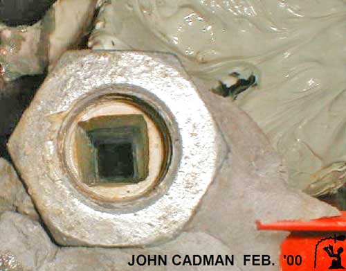
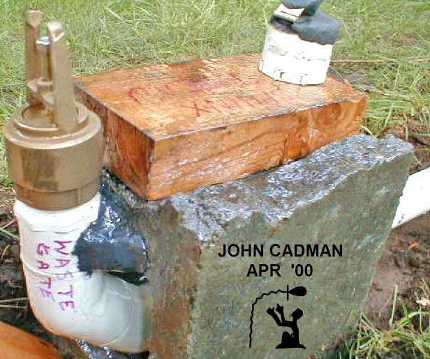
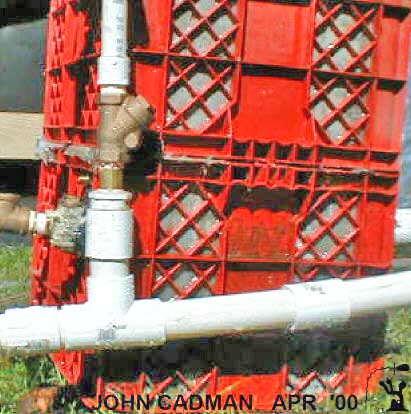
FIGURE 12. The Wastegate and the Bypass
 

(Left) The original wastegate was vertical with a variable weight utilized to reopen the valve. Later, the valve became horizontal with no weight, utilizing only the rarefaction wave to reopen valve. The vortex of the subterranean chamber would spin the valve 30’ down the line. (Right) To compare the pumping unit with the subterranean chamber in place versus without, a straight pipe was fit in place where the room would have been. This resulted in a much simpler assembly that still pumped. There were two main differences. There was a large reverse pulse at the reservoir and the output flow was more erratic. This demonstrated how the subterranean chamber absorbed much of the reverse pulse.
 

Back to Contents