|
Colorado Springs Notes
-
September 1-30, 1899
Colorado Springs
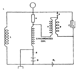
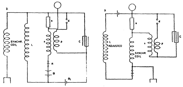
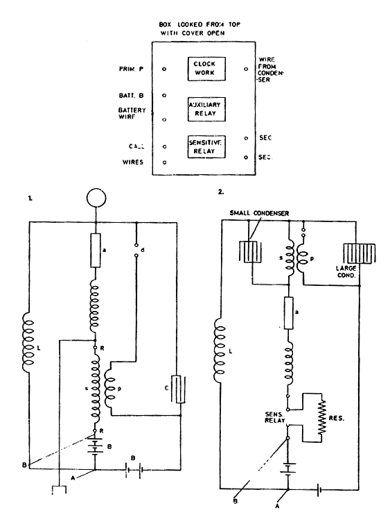
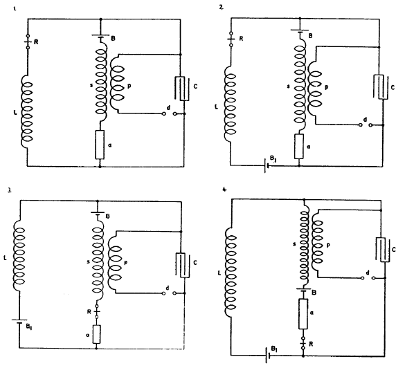
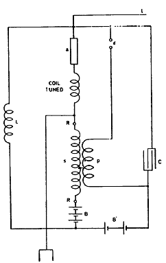
In Fig. 1 the defect is that no initial excitation of the condenser is provided for, which makes it difficult to employ a sensitive device of very high resistance which, for other reasons, is desirable. This fault is overcome in Fig. 2. by providing an additional battery B{ for charging initially the condenser and thereby exciting device a to the point of breaking down.
Still in the latter diagram there is the inconvenience that the relay is traversed by a pulsating current during the time when device a is not excited.
The improvement illustrated in Diagram 3. does away with this
drawback and this makes it possible to adjust the relay much better.
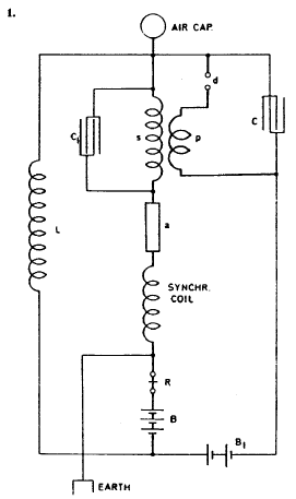
Still the relay by its self-induction is apt to interfere with the
vibration of the tuned secondary s. This consideration led to the
modification illustrated in Diagram 4.
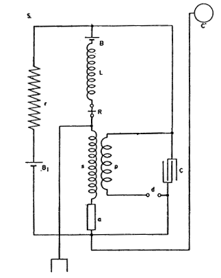
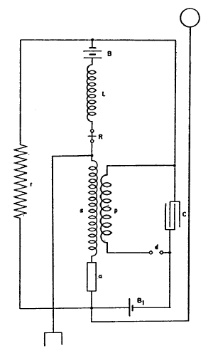
In this plan all the advantages so far aimed at are successfully
realized. The secondary is free on one end towards device a and the
potential rise can freely take place; the earth and air connections
are both very advantageously situated; the condenser is excited
exactly to the degree desired by adjusting resistance r. The
vibration of the secondary is not sensibly affected by attaching the
air line and capacity C, and the current through the relay is made
small by opposing batteries B and B1.
The device a was here chiefly strained through the induced currents in J .the strength of these being graduated by adjusting resistance r. Therefore the strain by the batteries themselves was insignificant.
Now these batteries were connected either so as to add together in charging the condenser when device a was diminished in resistance, or they were made to oppose each other. In the former case a small diminution of the resistance of a tended to produce a change in the same sense and the apparatus possessed the feature of self-excitation, while in the latter instance when device fell in resistance, the condenser charge was diminished and the excitation ceased automatically.
This secured small current through
the sensitive device. Any condition could however be readily secured
graduating, the batteries.
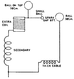
The spark gap being about 8 feet. As both oscillator secondary and extra coil vibrated the same period but were displaced in phase sparks passed readily and the vibration was that due to each separately, the harmonics being practically prevented to pass to earth.
An experimental coil was then fastened to the water pipe with one end and the adjustment for the same period was made. The coil was so placed as to exclude any inductive effect from the vibrating system so that the vibration in the coil was due only to that transmitted through the water pipe. The wire on the coil was previously wound upon a drum approximately 25 1/4 inches in diameter, there being 516 turns of wire No. 21, res. 45 ohms all wound in a single layer.
This coil gave on the free end
with induction from vibrating system aiding the vibration a
spark of 3/4"; with the induction eliminated the spark was fully
3/8" long. The spark on the water pipe itself was scarcely visible,
say 1/64" long, so that the coil increased the pressure many times.
The self-induction
was now nearly 20 times greater, and as the resistance was the same Lp/R was to be much
greater. It was feared though that the effect of distributed
capacity which was largely increased would be detrimental to the
rise of potential on the end. This proved to be the case so that it
appears again imperative to overcome also in the receiving circuit
the distributed capacity. Various ways are now to be experimented
upon with this object in view.
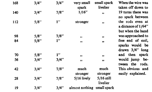
The sparking distance was observed from free end to body of experimenter, next from water-main to body, next between the two wires and finally with body of experimenter connected to free end, the spark between the same points. As it was sure that the vibration of coil was too slow for the impressed vibration of approximately 50,000, wire was gradually taken off.
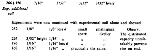
Indications up to present confirm detrimental effect of capacity. A coil was now added in series. This coil was one used often in New York and was wound on a drum 30" diam. There were about 150 turns total length of wire 1125 feet.
To this added the 266 turns of experimental coil giving length of 6.5 feet per turn made length 2100 feet for exp. coil or total 3225 feet. This was very near quarter wave length as it ought to be. Now results were
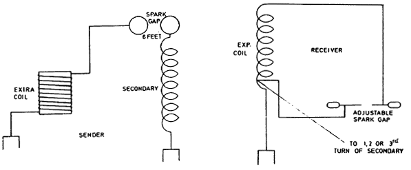
To observe better the end of coil which was before connected to earth (or water pipe) was now connected to a wire run from one turn of secondary, that is from the turn which was nearest to earth connection of secondary.
The connection was in the previous experiments as illustrated in one, then it was changed to the connection shown in 2. Nothing was, in principle, changed by this connection, only a higher e.m.f. (initial) was obtained and the tuning was made easier. This I have found to be an excellent way to adopt in tuning coils. The results were as follows:
The general conclusions already arrived at before were still further
confirmed by-these experiments.
Plan of connections:
The coil had nearly 1/4 wave length and the response was at once good,
a 6" spark being obtained from the free end, also between both ends
of coil. The spark would have been probably longer but this was the
limit to which the gap could be adjusted.
A still smaller capacity was now used in
the belief that perhaps the 4" ball was too large but the
experiments showed a contrary result. It was thought that the wave
length being estimated from that of the oscillator and extra coil
must be longer than that of the wire on experimental coil. This led
to consideration of certain advantages of long waves allowing a
great length of wire to be wound up on the experimental coil, this
in certain instances overbalancing the advantages of the larger
magnifying factor which the short waves offer.
It was now important to get an idea of the magnifying ratio and the
spark was tried on the water pipe and on the free end of coil and
the lengths compared. On the water pipe it was 1 /64" and on the
free end 1 1 /2". This was fair but the coil was not yet quite well
tuned. Completing the adjustment with more care the spark on the
pipe was found 1 /100" and on the free end of the coil 2". This was
quite satisfactory but not the best by far.
This capacity did not secure the best vibration of the sender which was a little slower but was suitable for the coil and no further attempt was made to tune still more advantageously by winding up more turns on the experimental coil. An important fact not to be forgotten is that the experimental coil responded without any spark passing between the oscillator balls.
Obviously it was seen that, although the experimental coil during the tuning was placed so as to avoid induction of the primary system, the same still existed to some extent. To ascertain how much induced e.m.f. was set up spark was first tried between the terminals of the coil without ground connection and the spark obtained was about 1 /64".
Now the coil was
reversed so that the induced
e.m.f. was against the directly communicated e.m.f. through the
water pipe and it was found still that a spark of 1" between the
rods was obtained. The same would have been probably longer had it
not been for the fact that the end of the coil was influenced by the
metal of the sink which was near. As this could not be helped the
effect could only be approximately estimated. All this showed that
the induced e.m.f. from the primary system was not to any
considerable degree responsible for the rise of pressure on free end
of experimental coil.
At a distance of 400 feet the spark without capacity was still 1/8" and with capacity of experimenter 1 /2" although at one place the pipe was buried for 30 feet in the ground. Strong shocks were obtained at that distance before the point of connection.
The experiments having shown the effects of distributed capacity to be very hurtful if not fatal to success with tuned coils, for convenience a winding was adopted to give very small capacity and thus the greatest possible length of wire and highest potential on the free end without any capacity.
Capacity on the end was not needed since the free end is connected to a sensitive device practically without capacity. Since it was desirable to get the greatest possible rise of pressure on this device, it was much better to tune for a condition without capacity on the free end, for any capacity would cause diminution of pressure since the amount of energy was fixed.
But wound in this way the tuned coil was not quite
suitable to serve at the same time as secondary of the induction
coil and, to utilize older apparatus, finally the connection shown
in diagram on the left was adopted, which was found to be best.
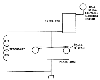
The tension on extra coil terminal ( a ball of 38 cm. capacity) was over 3 million volts, as was evident from streamers from ball. At a distance from the extra coil (8 feet) another ball 38 cm. capacity was supported, and this ball was joined by a heavy cable 400,000 circular mills section to the ground.
The cable was 120 feet long and was not straight but made 3 small turns about 4 feet diam. The rest was practically straight. As the ball connected to the thick cable could not be elevated as high as the other ball of equal size on top of the extra coil a spark-gap was established as indicated in sketch.
A small ball was joined to the cable leading up this ball being placed at about the height of the large ball connected to the thick cable. In estimating the vibration of the system comprising the large ball and thick cable leading to ground it was assumed for the present that the large cable was straight and self-induction calculated on this basis would, of course, give a smaller value, but this was thought sufficient to give the first idea as to how much wire should be placed on receiving coil.
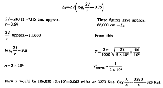
Assuming the cable straight we have
This wire is to be wound on a drum 10" diam. Therefore, we want
328 turns at least.
As
with this L the capacity would have to be extremely small, far less
than the coil evidently had, it was safe to proceed in taking wire
off. Gradually shortening the wire increased the spark length until
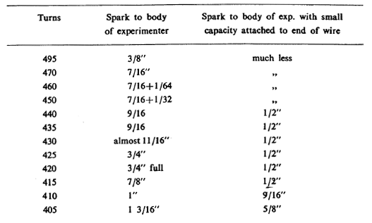
at 405 turns and a capacity of 15 sq. inches tinfoil the longest
spark was obtained about 1". Calculating from wire length λ/4 was
1010 feet approx. giving n =245,500 per sec. approx.
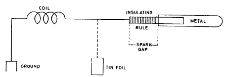
The spark was taken to the body of the experimenter, the length being at once read off by a simple arrangement comprising a small rule of insulating material and a metal strip, the position of which was adjustable relative to end of the insulating rule.
The metal strip was held in hand and the end of the insulating rule was maintained almost in touch with the wire forming the free terminal of the coil which was carefully placed in the proper position such that there was no induced e.m.f. from the primary but only through the ground connection could the coil be excited.
The connection of
coil and manner of reading off spark-length is indicated in the
above diagram.
With 405 turns the limit was nearly approached. With 400 turns the
spark without capacity was 1 1/4" and with tinfoil on wire 5/8";
with 395 turns the former was 1 1/4" the latter 5/8" and with 390
the same also, with 385 practically the same. The system still
needed a small capacity for when a hand was held at a distance of
about a foot a spark of 1 3/8" could be obtained.
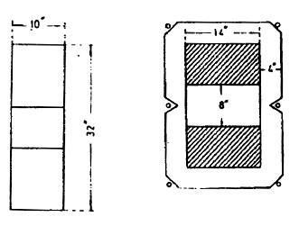
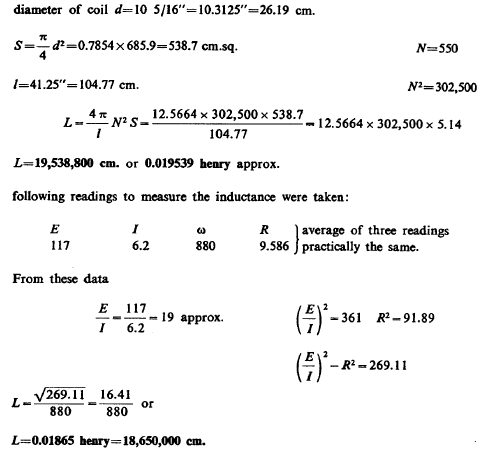
The coil was wound on a new drum 10
5/16" diam. and 41 1/4" length. There were 550 turns of No. 18
wax-covered wire.
The tests showed that without any capacity or wire the disturbances were recorded about one mile away; only the ground connection was essential as the waves were still fairly long, about 4000 feet (approx.)
The extra coil was now adjusted to the same vibration. As with the ball lifted up the vibration was somewhat too slow for the secondary, the ball was lowered to about half the height when resonance was secured with nearly the same capacity and self-induction in primary circuit as corresponded to the vibration of the secondary. Although the agreement was not quite close, the effects were remarkable.
The
streamers went from ball 38 cm. capacity on top as freely as though
it were a small one, this showing that the e.m.f. was far in excess,
possibly many times the 3 million volts which theoretically are
necessary to produce streamers from a ball of this radius of
curvature.
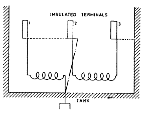
This was recognized as necessary as the one half previously used did not load 2 the jars quite fast enough as was evident from the measurement and calculation of constants. When the parts are used in multiple arc the 1i connection is as illustrated by -------- lines. When the old connection was desirable the dotted connections were taken off and the connection indicated by .. .. line.
A further change was made today by n
substituting for the 5" pulley on the alternating motor another pulley of 6". This gives now
The resonance of secondary was obtained with all jars or tanks (8 on each side) and 6 turns self-induction, while resonance of extra coil with ball elevated took place with all tanks likewise and 4 turns self-induction. The coil was still a little faster than the secondary. When both were connected in series the effects were magnificent, streamers up to 12 feet from the ball. To get best effect a middle value of self-induction had to be inserted, but although with this number of turns (about 4) both the secondary and extra coil were weakened individually, their joint effect was much stronger.
This showed
importance of very close tuning.
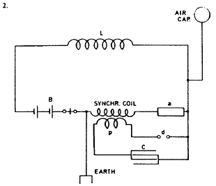
These diagrams are self-explanatory. In all of
them both the secondary coil and synchronized coil have their ends
free for the purpose of enabling great size of pressure. This has
been found a great advantage as has also the construction of a
resonating coil in which distributed capacity is reduced to minimum.
This latter advantage is secured to a large extent also when
an independent induction coil is used, as in following diagram (1):
The lettering is as in previous diagrams. A small condenser C, is
connected to secondary to allow easy passage to the high frequency
currents from the ground through the synchronized coil to the
sensitive device and wire or capacity in the air.
Remark: Another battery is sometimes placed in synchr. coil circuit
(this is not shown).
A board was provided to close up this part and on the board was mounted: sensitive relay, clockwork driving break and sensitive device, also a special circuit interrupting device.
These boxes were merely made
for the
investigation outside and such use. The synchronized coil was wound
in one instance' around a drum 10" in diam. and about 4 feet high
from the ground and carrying on top a board for placing the box with
the instruments and supporting a light rod for air or capacity wire.
In another form of apparatus the synchronized coil was wound on drum
of 2 foot diam. and 18" high, which was supported on a tripod of
photographic outfit.
The experiments fully confirm this. In the tests the capacity of the two balls
of 18" diam. did not very materially derange the adjustment and
period of the circuit. This is to be expected; as for the secondary
the capacity was far too small and on the other hand the independent
vibration of the extra coil could not be materially interfered with
since the condenser formed by the two balls and zinc plate allowed
free passage of currents to earth. Now the important thing was to
decide whether it is better to make length of extra coil one half or
one quarter of wave as before. This to be thoroughly investigated.
The working
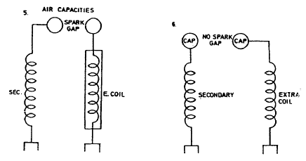
In Figs. 2. and 3. the vibrations through the
ground are intensified by the extra coil working directly on the
ground either through a gap with capacity or without same. In all
cases it has been found important to have the two systems vibrate in
synchronism. The same considerations apply to Diagrams 4, 5 and 6.
The plan in Fig. 1 being found best, the question is what is the
best give to the wires.
With the
extra coil 1/2 wave length and the secondary
1/4, they both cooperate on the condenser producing on the ball a
much greater pressure. This appears the best relation in Fig. 4. In
Fig. 5. and 6. it is found best to make extra coil 3/4 wave length
and the secondary 1/4 for obvious reasons.
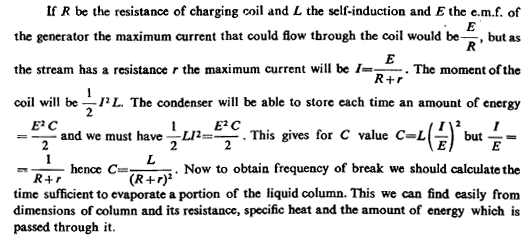
The stream is broken by condenser current. The plan followed for some time was to produce the stream automatically by a magnet worked by a key.
The connections are schematically indicated in the diagram. The question is to get the proper capacity of condenser, the amount of self-induction and other particulars. The secondary of the oscillator may be connected as shown to the ground and elevated object of capacity or else a spark gap may be used.
(This to be followed out.)
The approximate area of pipe above the roof will be:
π x 20 x
12 (6+5+4+3+3+ M + 2)= 17,332 sq. inches or 120 sq. feet. The ball
having nearly 20 sq. feet. We shall have 140 sq. feet+cap. There
may be possibly 150 sq. feet with all joints. The electrostatic capacity will reduce
turns on coil to probably less than one half.
The diameter of the new coil is to be exactly 15 meters inside of wire or about 49.25 feet. Two turns of primary are to be used as before, generally connected in multiple. Provision is made for 48 turns of secondary. Twenty two of the new turns will be equivalent to the 25 turns used last on tapering frame.
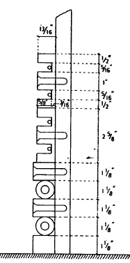
The frame is being
built up as in sketch. The primary cables separated by pieces 1 1/8"
thick. The secondary wire No. 10 used before to be wound in grooves
provided in mouldings as shown. Two groovers were provided in each
moulding this making the work simplest. Space was provided for two
wires in each groove as it might be found later necessary to double
copper. Primary and secondary are to have same amount.
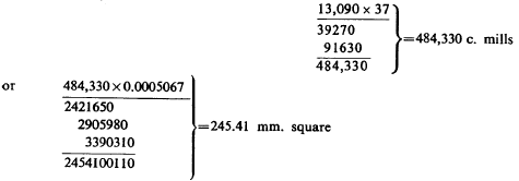
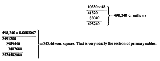
Taking one wire in each groove (No. 10 B. & S.) we have for 48 turns 10.380 mills being the section of wire No. 10 total section reduced to one turn
Therefore, if two primary cables are used there should be two wires
in each groove of the secondary as provided for. The total section
of primary will then be 490.82 sq. mm. and of secondary reduced to
one turn: 504.92 sq. mm., but as the wirjfis slightly stretched the
sections or masses respectively will be more equal.
There are three primary coils and 4 secondary
coils. For a transformation to 60,000 volts a part y
of primary is left out. Best way of working is to use smaller
transformation ratio to 45,000 approx. The secondary coils are
connected up alter
natively, that is, beginning with the first on the left, then to
third, then to second and from there to the fourth coil.
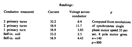
Measurement of self-induction of primary of oscillator and regulating self-in. coil.
Of the above readings the one showing 58.9 amp. was taken repeatedly and is very probably closer than the other reading with smaller current. Taking this as the-basis I find, neglecting resistance of both primaries and self-in. coil being very small L2p of two primaries:
As there are 24 turns we may take as a rough approximation when quickly computing: 3600 cm. per turn when there are a considerable number in.
This system is then excited by a primary vibrating system in a convenient manner and one or both of the elements of the excited system is varied until resonance is obtained. This gives the period of the primary system and if in this only one more element is known all the others can be easily determined.
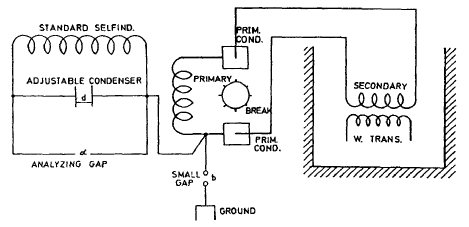
The excitation is conveniently secured and graduated by connecting the wire leading to the system to be excited to the ground through an adjustable spark gap, which is generally very small.
This method was applied to determining the period of the primary system used in these experiments in the following manner: a standard self-induction coil made long ago and used in experiments in N.Y. about 1560 turns wound on a drum 3 1/2" diam. was shunted by the adjustable condenser, also frequently used and consisting of two brass plates 20" diam., and this system was connected to one of the terminals of the Westinghouse transformer as illustrated in diagram below.
By varying the length of spark at b the degree of excitation was varied to any value desired, the spark at a serving to determine maximum rise of potential on terminals of excited system.
The difference must be due to the internal capacity of the coil or
possibly inexactness of the dimensions above.
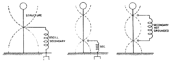
This point
should now be so located that there is at the same moment, say, a
position maximum on top and a negative on the bottom or ground, that
is the top and bottom should be one half of the wave apart or a
multiple thereof.
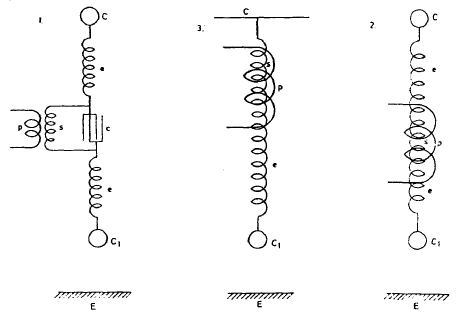
The arrangements furthermore contemplate doing away with the spark which consumes energy, although in many respects it possesses advantages giving, in particular, a very high rate of energy delivery. In the diagrams three such arrangements which have been experimented with are illustrated.
In Fig. I. the form of connection is shown most frequently experimented with here. The primary p energizes secondary s shunted by condenser c, the secondary exciting extra coils e e with their capacities C, at the free terminals, one of which, C1, is at some distance from the ground or groundplate E forming a condenser with same. All the three systems, primary, secondary and extra coil have the same period of vibration.
Fig. 2. illustrates a simplified way; in this instance the extra coils are partially influenced by induction from the primary p. In Fig. 3. again the extra coil e may be only electrically or also inductively excited. The upper terminal is here a very large capacity as the roof of a building and the terminal of high potential is C1.
|








 breaks per
sec. The
tests showed best results with secondary of oscillator, 8 tanks on
each side self-ind., 6 turns in. Streamers were all along on the top
wire which was raised today, very strong, more so than before.